BBU vs UPS for AI Servers
Rack-level seconds versus room-level minutes — the BBU vs UPS tradeoffs for AI server backup in one table.
Two Backup Architectures, One 48V Decision
The OCP Open Rack V3 BBU Shelf spec Rev 1.1 fixes the rack-level backup in 48V: the shelf sits on the same DC bar as the CRPS and holds up GPU trays for the few seconds a generator needs. The 48V ORv3 power architecture replaces the old 12V tray bus, so a BBU must be specified at 48V, not adapted from a 12V UPS. A central UPS protects the room-level feed, but it converts AC to DC and back to AC, adding a conversion layer between the utility and the rack.
The engineering tradeoff is time and location. A BBU reacts at the rack busbar in sub-cycle and covers the generator start window; a UPS rides through outages for minutes from a central battery room. For AI racks crossing 120 kW per cabinet, the room-level path carries enough distribution loss that a 48V BBU becomes the mandatory first line. The table below puts the two architectures side by side for procurement decisions.
Side-by-Side: BBU vs UPS
| BBU rack-level | UPS room-level | Notes |
|---|---|---|
| Location: inside rack (ORv3 shelf) | Location: central battery room | Distance from rack adds distribution loss |
| Response: sub-cycle 48V DC | Response: transfer switch time | BBU avoids AC/DC/AC conversion |
| Ride time: seconds | Ride time: minutes | Size BBU to generator start window |
| Efficiency: single conversion | Efficiency: double conversion | 48V ORv3 reduces losses vs 12V |
| Footprint: 1U shelf per rack | Footprint: dedicated UPS room | At 120 kW per rack, room space is scarce |
| Maintenance: hot-swap BBU shelf | Maintenance: battery technician visits | BBU MOQ 50+ from Shenzhen |
| Cost: per-rack capex | Cost: centralized capex | BBU scales with GPU rack count |
| Best for: AI racks >120 kW | Best for: campus ride-through | ORv3 48V replaces 12V for GPU trays |
Reading the Architecture Schematic
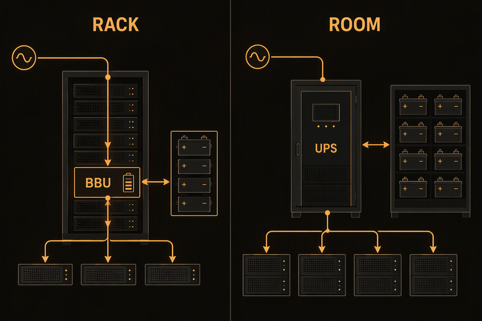
The schematic shows the 48V ORv3 bus supplied by a CRPS power supply, with the BBU shelf connected in parallel on the same DC bus. The central UPS and PDU feed building loads, not the GPU tray bus. When the utility feed drops, the BBU holds the 48V bar at the rack while the generator ramps; the UPS continues to carry cooling and room load.
- Left rail: AC feed → CRPS → 48V ORv3 bus to GPU trays
- Middle shelf: OCP BBU Shelf ties to the 48V bus with no transfer switch
- Right side: central UPS + PDU handles room and cooling loads
Decision Rules for 48V Backup
- Above 120 kW per rack, put the BBU shelf on the 48V GPU tray bar.
- If generator ramp takes 30 seconds, BBU ride time covers the gap without a room-level transfer.
- For OCP ORv3 GPU trays, use a 48V BBU shelf following the Rev 1.1 spec.
- One 1U BBU shelf per rack beats a dedicated UPS battery room for an AI pod.
- For a retrofit 12V rack, add the 48V ORv3 BBU only when rewiring tray power.
Model Your 48V Backup Mix
Send DC Power your 120 kW rack count and generator ramp target — we'll spec BBU shelfs and UPS options with Shenzhen factory lead times.